

A pipeline outage rarely arrives at a convenient time. A construction project may be approaching an occupancy milestone, an industrial process may need fuel to protect equipment, or a utility may have to maintain service while permanent infrastructure is unavailable. Within a short window, a temporary CNG or LNG system can become the difference between controlled continuity and a serious operational disruption.
The pressure to connect quickly is understandable. It can also create unsafe shortcuts. Mobile gas equipment isn't a plug-and-play appliance. It becomes part of a changing site with temporary piping, vehicle movements, electrical dependencies, weather exposure, unfamiliar personnel, and decisions made under time pressure. Safety reliability and risk analysis must therefore address the complete deployment, not just the trailer, tank, regulator, or hose.
The High Stakes of Temporary Natural Gas Deployments
A temporary gas deployment often begins with a phone call about a failure somewhere else. A main line is unavailable, a construction connection is delayed, or a facility needs fuel while maintenance work continues. The project manager has a schedule to protect, the utility partner needs a practical contingency, and the site team wants a clear answer: when can fuel flow?
That urgency can distort priorities. Teams may focus on delivery time and equipment availability while treating the site survey, connection review, emergency planning, and commissioning checks as administrative tasks. That approach is dangerous because the hazards don't come from one item in isolation. They arise at the interfaces between the mobile unit, temporary piping, electrical systems, traffic routes, workers, contractors, weather, and operating procedures.
The first question shouldn't be, “How quickly can we place the unit?” It should be, “What must be true before this unit is connected and pressurized?”
Three outcomes must stay aligned
A sound temporary gas program has three operating objectives:
- Protect people: Identify credible events such as hose rupture, overpressure, loss of containment, ignition, and vapor dispersion, then assign effective controls to each one.
- Maintain fuel continuity: Confirm delivery access, refill planning, pressure monitoring, equipment availability, and contingency actions before the first load arrives.
- Prevent environmental incidents: Control leaks, establish response arrangements, and make sure personnel know who can isolate the system and escalate an emergency.
These objectives can conflict. A shortcut that saves commissioning time may increase the chance of a connection error. A layout that simplifies vehicle access may place equipment closer to active work. A procedure that depends on one experienced operator may fail when a contractor changes shifts.
Practical rule: Speed is valuable only when the deployment can be commissioned, operated, monitored, and shut down under the actual conditions at the site.
A useful HSE review should also clarify who owns each control. Teams that are building a broader safety process can use this guida alla compliance per HR e HSE as a reference for organizing risk responsibilities and documentation. It doesn't replace a gas-system hazard assessment, but it can help connect site safety duties with the temporary deployment plan.
Learning from Aerospace to Build System Level Reliability
Probabilistic risk assessment emerged from U.S. aerospace and missile programs in the early 1960s. Its history offers a warning that applies directly to temporary gas systems: a numerical result can look precise while still being weak if its assumptions, data, or system boundaries are poor.
During the Apollo program, NASA commissioned a quantitative assessment of the probability of landing astronauts on the Moon and returning them safely to Earth. The estimate placed mission success at less than 5%, equivalent to fewer than one successful mission in 20. NASA considered that result excessively pessimistic and relied more heavily on qualitative techniques, including hazard analysis, failure modes and effects analysis, engineering reviews, and extensive component testing. The episode shows why risk analysis must support design discipline and operating controls, rather than replace them. NASA's review of probabilistic risk assessment documents this broader lesson.
Component reliability isn't system reliability
A regulator can perform well in a test and still form part of an unreliable installation. The connection may be damaged during handling. A hose may be routed through a vehicle path. A detector may be affected by its surroundings. An emergency shutdown may depend on a shared power supply that fails with the control system it is meant to protect.
Historical rocket data makes the point clearly. NASA's review found that approximately 2,900 solid-rocket flights included 121 failures, about 4.2%, or roughly one failure in every 24 flights. That fleet-level evidence provided a more realistic basis for reliability estimates than optimistic assumptions about individual parts. In a series system, where every critical element must function, overall reliability is the product of the individual reliabilities. NASA's historical reliability analysis explains why component performance cannot establish system safety by itself.
For a mobile CNG or LNG installation, the system boundary should include:
- The fuel source and transport interface, including delivery, positioning, and connection conditions.
- The temporary piping and hose assembly, including supports, routing, coupling protection, and pressure control.
- The customer equipment, such as burners, generators, process equipment, or heating systems.
- People and procedures, including commissioning, shift handover, inspection, and emergency response.
- The surrounding environment, including weather, traffic, excavation, ventilation, and electrical availability.
Test the whole arrangement
A strong reliability review combines failure likelihoods with structured hazard identification. Aerospace programs used simulated environments, failure reporting, corrective-action programs, design reviews, and integration of component and subsystem reliability data. The mobile-gas equivalent is a documented review that asks whether the equipment still works as intended after transport, placement, connection, exposure, and handover.
The practical output shouldn't be a single reliability percentage. It should be a list of credible failure modes, the conditions that make them more likely, the consequences if they occur, the controls that prevent them, and the evidence that each control works. Independent review is especially valuable when the installation is being assembled under schedule pressure or when the site layout differs from previous deployments.
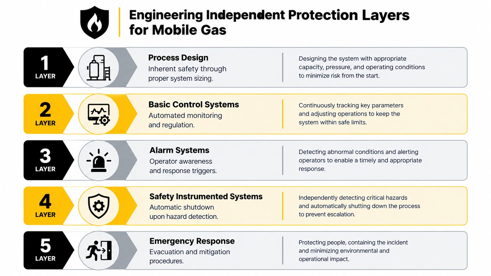
Engineering Independent Protection Layers for Mobile Gas
A documented hazard-and-risk assessment should exist before a temporary gas system is deployed. Start with the credible hazardous events, then determine which protection layers prevent each event, detect it, isolate it, or limit its consequences. This is more useful than treating “leak detection” as a complete safety strategy.
For example, a hose rupture may require excess-flow protection, automatic isolation, emergency-stop coverage, gas detection, and a response plan. Overpressure may require correctly selected relief protection, pressure monitoring, control-system action, and a defined escalation path. Vapor dispersion requires attention to release location, ventilation, ignition sources, detection, exclusion zones, and emergency access.
Allocate protection by function
IEC 61511 guidance uses Safety Integrity Levels to define the required performance of safety-instrumented functions. The risk-reduction factor is the relationship between the unmitigated or intermediate-event likelihood and the mitigated likelihood. For a temporary CNG or LNG installation, a function assigned SIL 1 targets at least a 10-fold risk reduction, SIL 2 at least 100-fold, and SIL 3 at least 1,000-fold. These targets are not labels to add after equipment selection. They should follow the hazard assessment and the required safety function. The relevant IEC 61511 guidance sets out this risk-based approach.
A practical allocation table might look like this:
| Hazardous event | Preventive or protective function | Verification question |
|---|---|---|
| Hose rupture | Automatic excess-flow shutoff and remote isolation | Does the system isolate without relying on a nearby operator? |
| Overpressure | Relief protection and pressure monitoring | Are set points, discharge conditions, and inspection status documented? |
| Loss of containment | Detection, isolation, and controlled response | Can personnel identify the alarm and reach the shutdown point safely? |
| Ignition after release | Source control, separation, and emergency response | Have ignition sources and access routes been reviewed for the current layout? |
| Vapor dispersion | Ventilation review, detection, and exclusion controls | Does detector placement reflect the actual release and airflow conditions? |
Independence is the part teams miss
Five safeguards aren't five protection layers if they depend on the same weak point. A shared power supply can defeat monitoring, alarms, and automatic isolation at once. A common sensor fault can undermine more than one function. The same maintenance error can leave several nominal safeguards unavailable.
For each assigned layer, ask:
- Does it use a separate initiating signal or detection method?
- Does it depend on the same power, control system, communication link, or valve?
- Can one maintenance error disable multiple layers?
- Is the function tested under the conditions in which it must operate?
- Does an operator have a clear and timely action if the engineered layer fails?
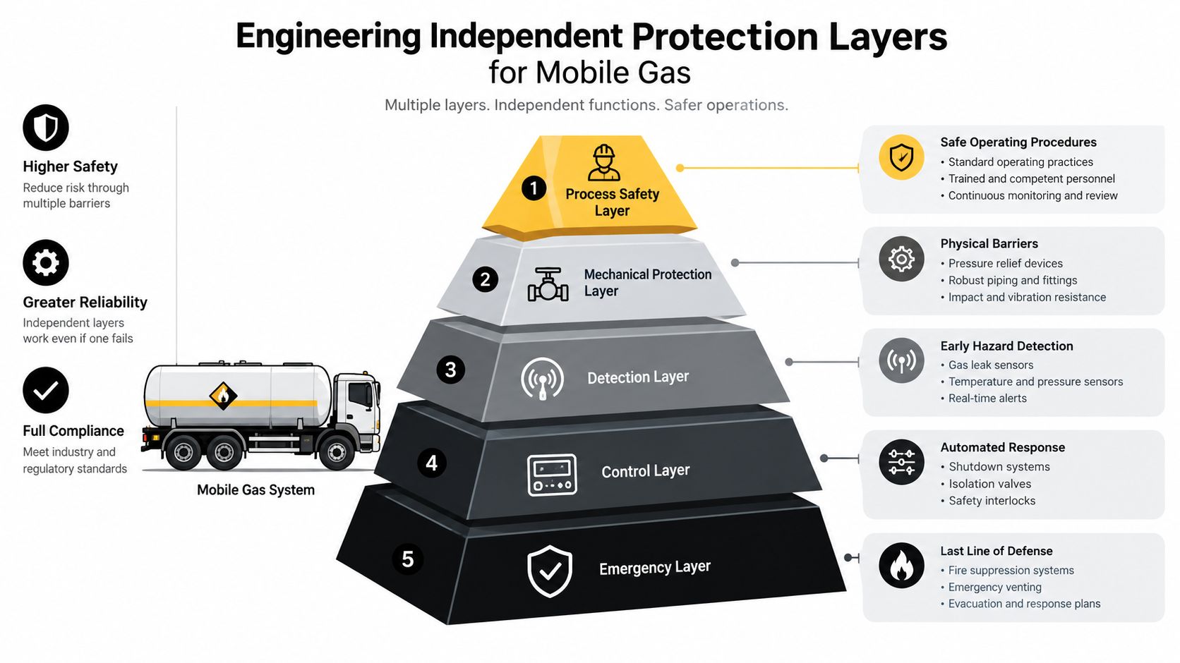
Procedures still matter, but they shouldn't carry the entire safety burden. An operator may be distracted, unable to reach the equipment, unfamiliar with the layout, or responding to multiple alarms. Engineered safeguards reduce dependence on perfect human action. The commissioning record should identify the responsible person, the test method, the result, and any restriction placed on operation when a layer isn't available.
Managing the Coupled Gas Electric and Weather Problem
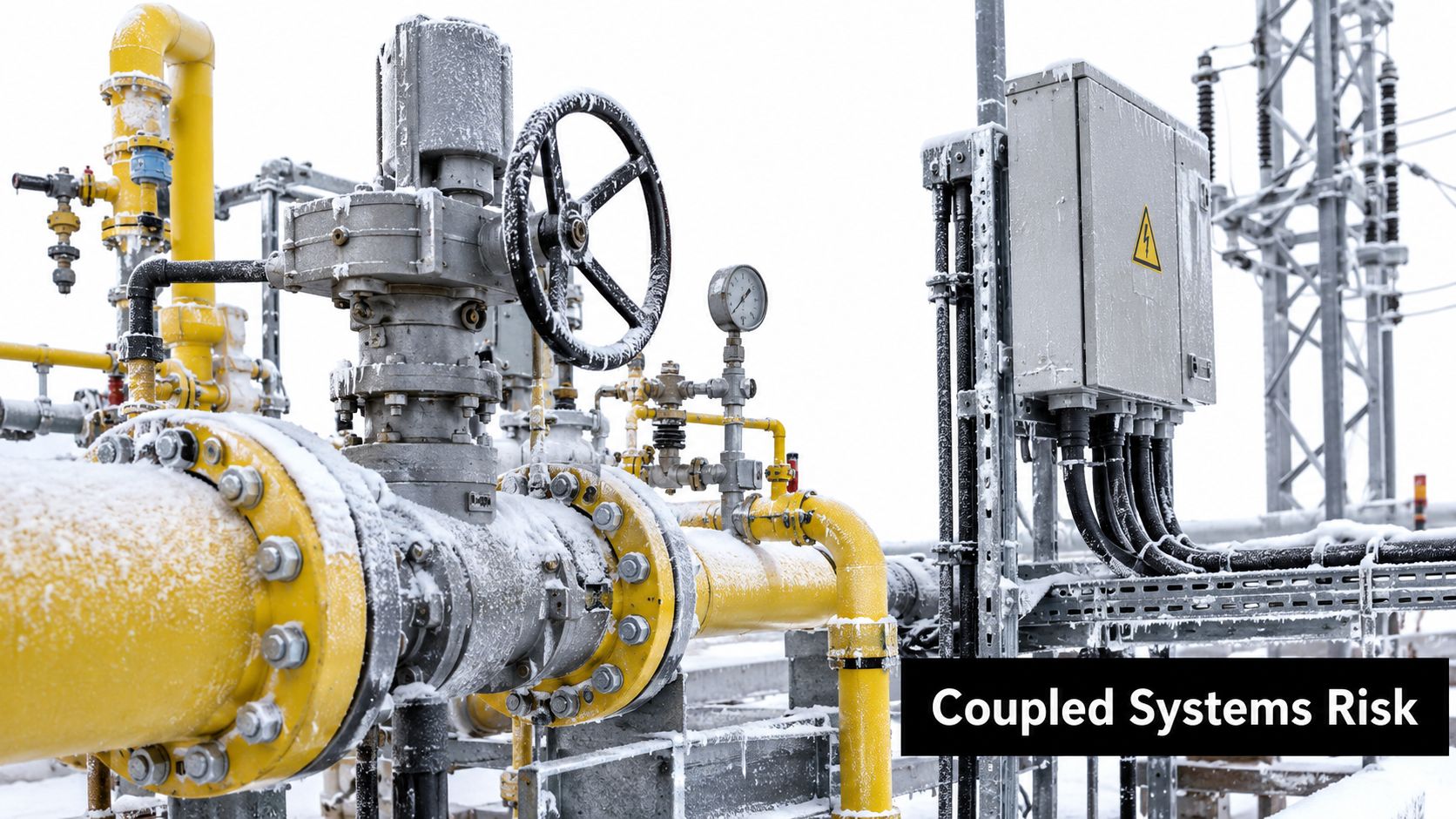
Temporary gas supply isn't merely a backup-fuel question. A mobile system may depend on electricity for compression, controls, detection, communications, or customer equipment while operating in weather that affects fuel delivery, access, pressure, and demand. Treating those dependencies separately can hide the actual failure scenario.
Freezing conditions can affect gas infrastructure and equipment. A loss of electrical power can reduce the availability of compressors or controls. Transportation delays can extend the time between refills. At the same time, heating demand may rise across the wider system, increasing competition for supply. The site-level risk is therefore a combination of weather, electricity, logistics, and demand rather than the failure probability of the gas unit alone.
Resilience can hide the risk
During the January 2025 Arctic events, U.S. natural-gas demand exceeded 150 Bcf/day while production fell to approximately 97 Bcf/day at the low point. The system avoided a major incident because storage, coordination, forecasting, and operational preparation helped offset the stress, as described in the FERC review of the January 2025 Arctic events.
That outcome doesn't mean the exposure was low. It means interventions worked. Project managers should convert those interventions into explicit site requirements rather than assuming the system will always absorb the disturbance.
A temporary deployment plan should define:
- Inventory requirements: How much usable fuel must be available before a weather trigger or delivery disruption?
- Refill lead time: What delay can the operation tolerate, and who monitors the route and supplier status?
- Pressure thresholds: Which pressure condition triggers reduced load, a refill request, escalation, or shutdown?
- Weather triggers: What forecast or observed condition requires an inspection, relocation, protection, or operating change?
- Alternate power: Which functions remain available if normal electricity fails, and how are they tested?
- Demand priorities: Which loads are protected first if fuel or power becomes constrained?
Model simultaneous failures
A useful review combines probability and consequence across several hazards. For example, a freeze can increase heating demand, delay a delivery, affect electrical equipment, and reduce the time available to respond to a pressure problem. Each event may be manageable alone, but the combination can exceed the assumptions used for a normal deployment.
The control room, site manager, gas supplier, electrical contractor, and utility partner should agree on who monitors each condition and who has authority to change the operating mode. A plan that says “monitor the weather” without naming the decision-maker isn't an operational control.
Balancing Rapid Deployment Speed Against Active Site Risks
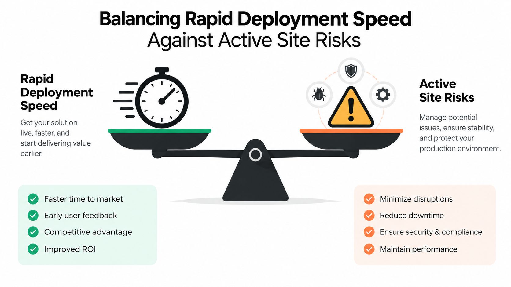
Rapid deployment has real value. Restoring fuel can protect construction progress, support commissioning, maintain heating, or reduce the consequences of a service interruption. But speed also introduces unfamiliar equipment into an active environment where layouts, personnel, vehicle routes, and work fronts may change.
The comparison should be explicit. On one side is the consequence of delaying temporary fuel. On the other is the risk introduced by placing, connecting, and operating mobile equipment before the site is ready. Neither side can be reduced to schedule pressure alone.
Use modeling to sharpen the decision
Sandia's HyRAM+ toolkit combines component-failure probabilities for compressed and liquefied fuels with models for heat flux, overpressure, release behavior, and flame physics. It supports facility safety planning and stakeholder engagement through a more integrated view of release consequences and equipment reliability. The HyRAM+ overview from Sandia provides the relevant background.
A model doesn't remove the need for field judgment. It helps the team ask better questions about the proposed layout, release locations, exclusion zones, ventilation, and nearby activities. For temporary work, the model or risk register should be revisited when the layout changes, not filed away after the initial approval.
Set go or no-go conditions
The commissioning decision should compare the site before and after deployment:
| Decision area | Before deployment | Go condition |
|---|---|---|
| Site interface | Identify traffic, excavation, lifting, and nearby work | The equipment and hoses have protected routes and controlled access |
| Gas connection | Review fittings, regulators, supports, and isolation points | Connection integrity is verified and documented |
| Personnel | Identify operators, contractors, and emergency contacts | Everyone with a response role has been briefed |
| Detection and shutdown | Confirm alarm and emergency-stop locations | Functions are tested and results recorded |
| Weather and utilities | Review forecast, power dependency, and delivery access | Triggers and alternate arrangements are defined |
A go decision should be withheld when a critical protection layer is unavailable, the exclusion zone cannot be maintained, emergency access is blocked, or shutdown ownership is unclear. A staged start can be sensible when the risk is controlled, such as beginning with a monitored load and expanding only after operating conditions remain stable.
The most effective commissioning checklists are standardized but not blind. They preserve the repeatable checks for hoses, regulators, connections, detectors, shutdowns, and communications while requiring the team to document site-specific changes. That balance allows fast mobilization without pretending every location is the same.
Transforming Incident Data into a Reliability Feedback Loop
A compliance record becomes valuable when someone uses it to change equipment, maintenance, training, or site controls. Federal pipeline reporting provides a useful model. The U.S. Pipeline and Hazardous Materials Safety Administration requires covered pipeline operators to report incidents within 30 days, using frequency, causes, and consequences to identify trends, plan inspections, and support risk assessment, as described in PHMSA's LNG data and maps resources.
Temporary gas operators can adapt that principle without waiting for a major incident. The data set should include both leading indicators and actual outcomes:
- Near misses: Record the event, location, operating phase, and immediate controls.
- Connection defects: Track hose, coupling, regulator, support, and routing problems by equipment type.
- Pressure events: Review excursions, abnormal trends, relief activity, and operator interventions.
- Detector alarms: Separate confirmed releases from alarms associated with ventilation, calibration, placement, or environmental conditions.
- Inspection failures: Record failed pre-use checks and identify recurring causes.
- Response performance: Measure whether the right person received the alarm, reached the shutdown, and communicated the required action.
- Actual releases: Document the commodity, cause, consequences, response, and corrective action.
The value comes from stratification. A coupling defect should be analyzed by equipment type, site conditions, weather, contractor, supplier, and operating phase. Repeated damage near a vehicle route suggests an interface-control problem. Repeated detector alarms in one layout may indicate ventilation or calibration issues rather than repeated releases.
Turn observations into maintenance decisions
Every recurring event should produce a defined action. Change hose routing, revise vehicle controls, alter inspection points, recalibrate a detector, replace a component, update a briefing, or change the commissioning sequence. The action should have an owner and a closeout record.
Trend analysis should also trigger management-of-change review when pressure, layout, suppliers, equipment, operating procedures, or site conditions change. A replacement component may have the same rating but a different interface. A new contractor may follow the written procedure differently. A changed work front may place traffic closer to a hose that was previously protected.
Reliability improves when near misses receive the same analytical discipline as failures.
The feedback loop is complete only when the organization checks whether the corrective action reduced the original exposure. That evidence should inform the next deployment, not remain attached to one project file.
Executing a Comprehensive Pre Deployment Safety Checklist
A pre-deployment checklist should be short enough to use in the field and detailed enough to stop an unsafe start. Assign an owner to every checkpoint, record the result, and treat unresolved critical items as operating restrictions.
Before equipment arrives
- Define the operating need. Identify the loads, expected operating mode, fuel continuity requirement, and consequences of interruption.
- Walk the site. Mark equipment position, hose routes, vehicle movements, exclusion zones, ventilation conditions, ignition sources, emergency access, and nearby work.
- Review the hazard register. Cover rupture, overpressure, loss of containment, ignition, dispersion, power loss, weather exposure, delivery delay, and human factors.
- Verify equipment condition. Inspect hoses, couplings, regulators, relief devices, supports, detectors, controls, and connection equipment.
- Confirm protection layers. Identify the shutdown functions, test method, responsible person, and evidence required for each layer.
- Set weather and supply triggers. Document inventory actions, refill escalation, pressure limits, alternate power, and reduced-load decisions.
A general GM GROUP Services audit template can help structure the wider site-audit record, but the gas checklist still needs equipment-specific tests and emergency controls.
During commissioning and operation
- Pressure up in a controlled sequence: Check for abnormal indications and stop when conditions differ from the approved plan.
- Test alarms and shutdowns: Confirm that signals reach the responsible operator and that isolation occurs as designed.
- Brief the workforce: Explain exclusion zones, alarm meanings, emergency contacts, vehicle restrictions, and who can authorize shutdown.
- Inspect at defined intervals: Pay particular attention to connections, hose routing, supports, detector status, pressure behavior, weather effects, and unauthorized site changes.
- Record deviations: A changed layout, contractor, power arrangement, or operating load should trigger review before the system continues.
At demobilization
Isolate and depressurize according to the approved procedure, verify the system is safe to disconnect, inspect equipment for damage, and capture near misses or defects while details are still available. Close the corrective-action record before the next deployment inherits the same problem.
Blue Gas Express provides temporary CNG and LNG delivery, gas-flow and leak-testing assistance, connection equipment, and coordinated LNG site preparation and monitoring. For a deployment that must balance rapid fuel continuity with documented site controls, visit Blue Gas Express to discuss the equipment and field support your project requires.