

The crew is ready, the test pump is on site, and someone asks which pressure starts the clock. The drawing shows the new pipe, but the temporary manifold, tie-in spool and isolation valve don't all appear on the same sheet. Before anyone fills the line, those details need a single, agreed answer.
For hydrostatic testing, pipeline boundaries, pressure calculations and hold records matter as much as the pump. A useful test doesn't just finish with a steady gauge. It leaves evidence of which pipe was tested, what happened throughout the hold, and who authorized the line's return to service.
Test Pressures and Hold Times at a Glance
Start with the maximum operating pressure (MOP) in the line's records, not the pressure someone remembers from normal operation. Hydrostatic testing uses non-flowing water above operating pressure to expose leakage and weaknesses before the pipeline carries its service fluid.
The PHMSA hydrostatic-testing fact sheet gives the hazardous-liquid requirements below: at least 125% of MOP for 4 continuous hours, an additional 4 hours at at least 110% of MOP where piping cannot be visually inspected for leakage, and an optional spike of about 139% of MOP for about 30 minutes when latent cracks or pressure-reversal damage are concerns.
Hydrostatic test pressure and hold time requirements
| Requirement | Test pressure | Hold time | Basis |
|---|---|---|---|
| Hazardous-liquid pipeline, primary test | At least 125% of MOP | 4 continuous hours | PHMSA |
| Hazardous-liquid, section not visible for leaks | At least 110% of MOP, additional stage | 4 hours | PHMSA |
| Optional spike test for latent cracks | About 139% of MOP | About 30 minutes | PHMSA |
| Natural gas transmission | Set by 49 CFR Part 192 Subpart J and the construction code | Set by the applicable Subpart J test provisions and construction code | 49 CFR Part 192 |
Work from the documented operating limit
For the fact sheet's 1,000-psi MOP example, multiplying by the primary-test factor gives 1,250 psi; an inaccessible segment also needs the 1,100-psi additional stage. Write the calculation beside the applicable requirement so the reviewer can check both the arithmetic and the reason for that stage.
Don't treat the optional spike as extra pressure that makes any test better. It needs an engineered purpose and an approved procedure suited to the pipeline's condition.
Water is used instead of gas because it releases less stored energy if a defect ruptures during testing. That advantage doesn't make a pressurized test assembly safe to approach without controls.
Natural-gas transmission requirements come from Part 192, Subpart J and the governing construction code. Don't copy hazardous-liquid multipliers into a gas test package.
Before filling, complete this check:
- Confirm the basis: Match the documented operating limit to the actual test section.
- Calculate each stage: Identify the required pressure, duration and acceptance criteria.
- Check the governing rules: Have the responsible engineer approve the values before the crew connects the pump.
How to Plan the Test Section and Set the Pressure
Planning determines whether the pressure result will mean anything later. A perfectly recorded hold on an uncertain boundary can't establish which pipe received the test.
Build a test package the crew can follow
Define the section physically. Mark tie-in points, valves, branches, high points and low points on a controlled drawing. Record pipe length and diameter, and identify each temporary connection. Walk the route against the drawing so a forgotten branch doesn't become an unplanned test boundary.
Establish rated isolation. Use blinds or valves suitable for the approved isolation arrangement, and confirm their pressure capability exceeds the planned test pressure. A valve's position indicator doesn't prove that its seat holds. Identify how the crew will detect passing isolation and protect adjacent equipment.
Pull the material records. Confirm pipe grade, specified minimum yield strength, wall thickness and the limits of fittings and other permanent components. Resolve missing or conflicting records before selecting a pressure. Raising pump pressure isn't a substitute for knowing the pipe's design limits.
Calculate the pressure against the governing requirements. Use the confirmed operating limit, location class, hoop stress and applicable code. The PHMSA pressure-test planning guidelines recommend evaluating whether the procedure can accommodate test pressures producing hoop stress up to 110% of specified minimum yield strength (SMYS). That's a stress-based engineering check, not a universal pump setting or a pressure unit.
Clean and gauge the line. Remove construction debris and verify the bore is suitable for the planned operation. Debris can obstruct instrument connections and drains; gauging can reveal restrictions. Neither cleaning nor a successful gauge run establishes that the wall is free of metal loss.
Plan the water before ordering it. Specify treated water with chemistry compatible with the pipe and connected equipment. Arrange freeze protection where needed, identify containment, and agree on treatment and disposal. The crew shouldn't discover that the discharge route is unavailable after the section is full.
Check the temporary assembly. Verify pumps, hoses, caps, manifolds and connections against the maximum planned pressure. Confirm gauge calibration, suitable instrument range and recorder operation. Include the temporary assembly on the boundary drawing rather than treating it as equipment outside the test.
Account for elevation and field decisions
Pressure isn't identical everywhere along a section with elevation changes. Establish the reference-gauge location, then calculate whether the high point receives the required pressure without overloading the low point or a weaker component.
Assign authority before starting. Name who controls the pump, who records readings, who can stop the test and who accepts the result. Establish communications and an exclusion zone appropriate to the approved procedure.
Practical rule: If the crew can't trace the test boundary on the drawing and on the ground, the test package isn't ready.
How to Fill, Pressurize and Hold the Test
The hold is a measured period, not a waiting period. The operator needs a defined starting condition, trustworthy instruments and a continuous account of anything that changes the pressure.
The fill, pressure rise and hold should follow one controlled sequence.
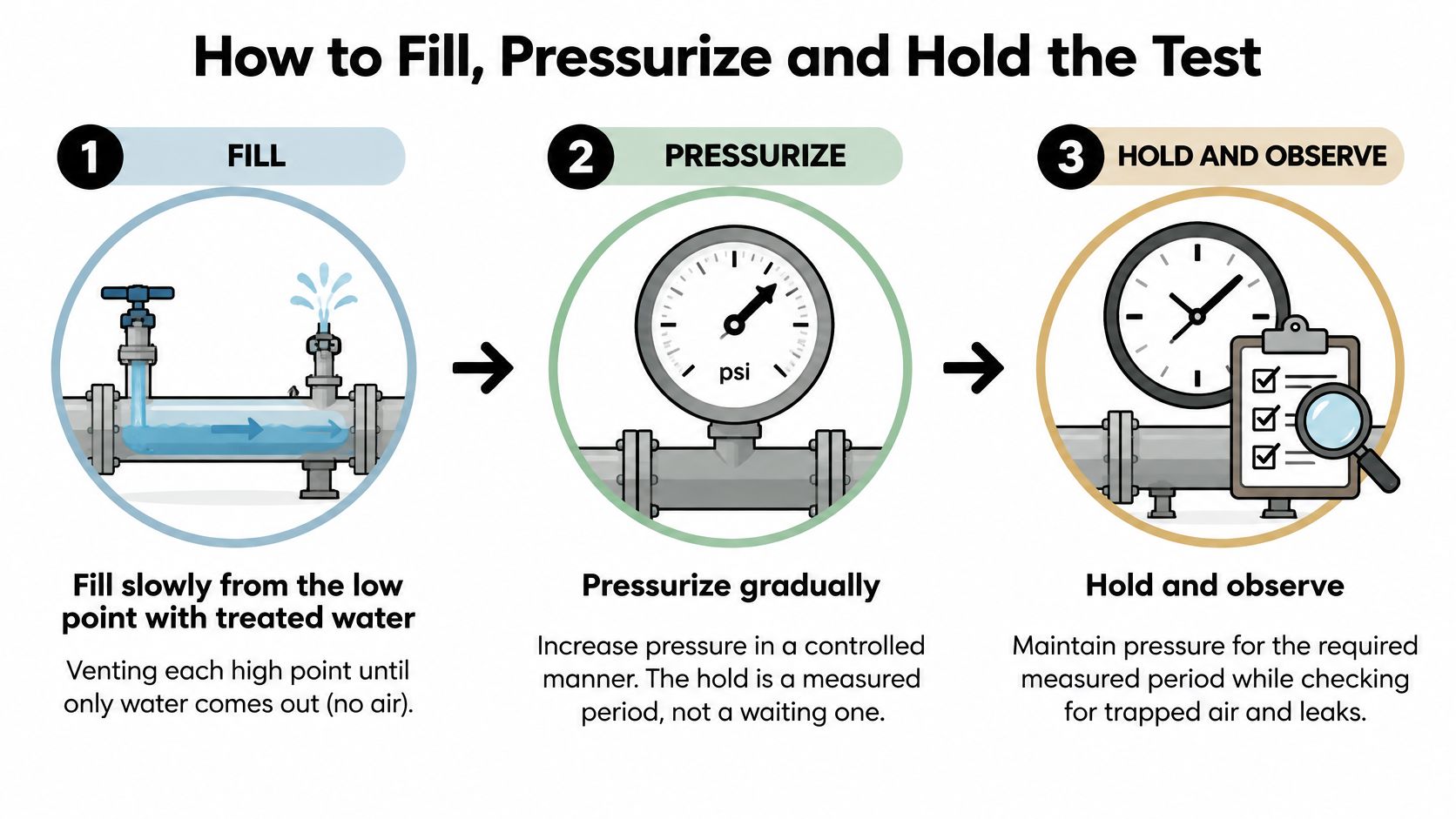
Fill and establish a stable starting condition
Fill slowly from the low point with treated water. Vent each designated high point until water flows without evidence of trapped air. Check branch and dead-leg venting arrangements rather than assuming the main vent clears everything. Air pockets increase stored-energy risk and reduce the sensitivity of the test.
Allow temperature and pressure to stabilize. Water delivered from a tank may be at a different temperature from buried or sun-exposed pipe. Heat transfer can move the gauge without a leak. Record the starting temperatures and use the approved stabilization criteria, not a guess that the crew has waited long enough.
Raise pressure in controlled stages. Pause at the procedure's checkpoints to review readings and observe the test assembly from safe positions. Keep people outside the exclusion zone during pressurization and never exceed the weakest component's allowable test limit. If a joint sprays, a hose shifts or a blind moves, stop pumping and depressurize through the designated route before anyone approaches.
Pressure-rated fittings need compatible threads, seals and assembly methods as well as adequate ratings. For background on fitting selection and test connections, the Yasu Trading guide to testing fittings from Yasu Trading Co. LLC is a useful companion, but the approved pipeline procedure controls the work.
Start the clock only when the conditions qualify
Confirm target pressure on the designated reference gauge. Cross-check it against the independent calibrated instrument and verify the recorder is running. Start the official timer only after the required pressure and starting conditions are established. Write down the actual start time rather than reconstructing it from the pump operator's memory.
Log the hold at defined intervals. Record pressure, temperature, pump volume, valve status and time using synchronized clocks. Identify who took each reading. Make observations meaningful: note whether a temperature reading represents water, pipe surface or ambient air, and keep the measurement location consistent.
Document every pressure adjustment. Don't top up the section to make the chart look flat. Record the time, volume added or removed, reason and resulting pressure, and determine whether the adjustment is permitted by the procedure. Undocumented pumping can conceal leakage and make the hold impossible to interpret.
Keep the pump operator available throughout the hold. A recorder doesn't replace supervision, and an unattended instrument can't explain a valve movement or a disconnected sensor.
A pressure drop isn't automatically a leak. Temperature movement, residual air and instrument problems can produce misleading readings, but none is an acceptable explanation without supporting observations.
The gauge is evidence. A pressure drop left unexplained means the hold hasn't demonstrated an acceptable result.
Inspecting, Depressurizing and Recording the Test
A test isn't finished when someone announces that the pressure held. The closeout must connect the chart to field observations, controlled depressurization and a complete record of the final condition.
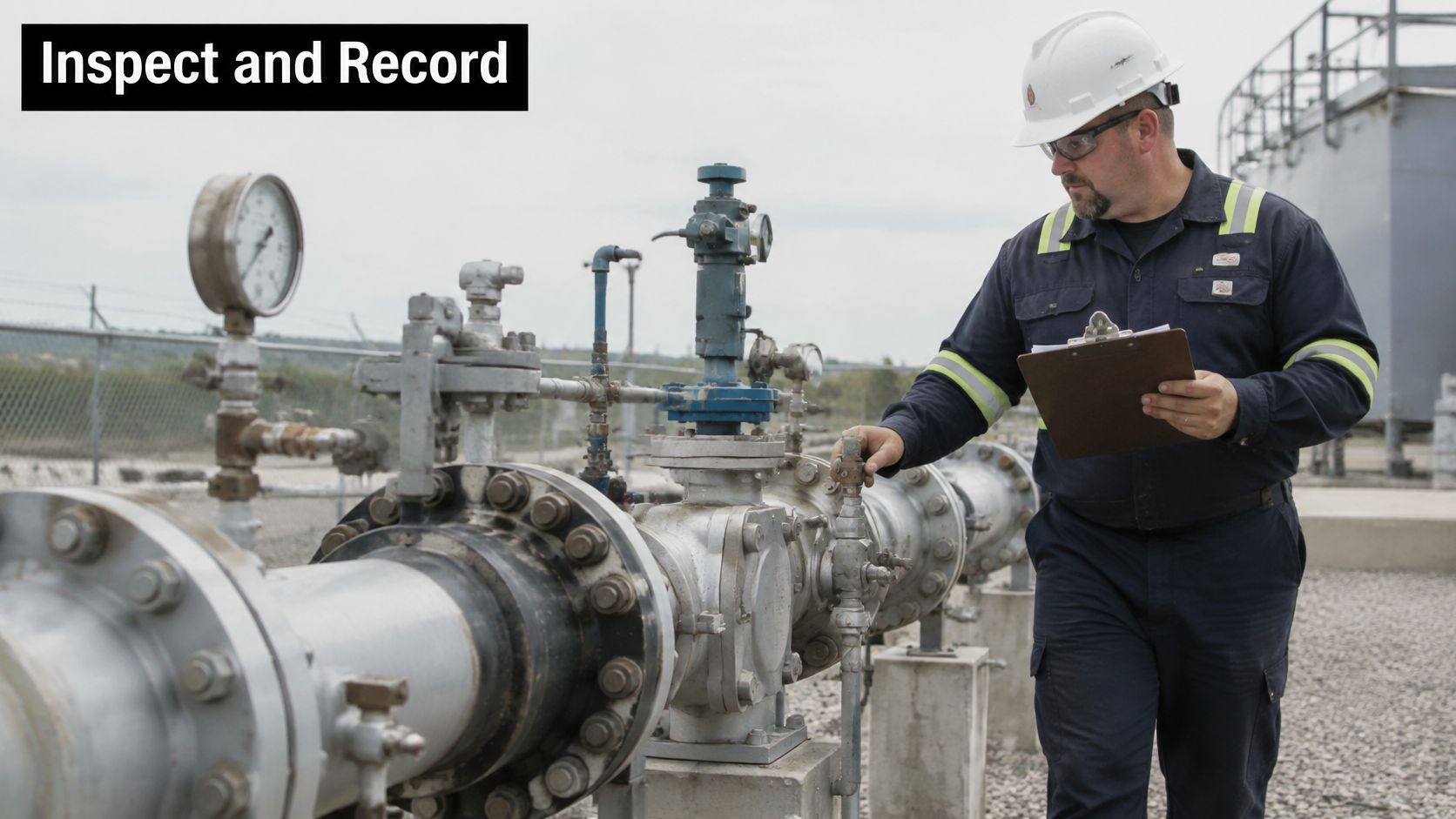
Inspect accessible joints, flanges, valves and fittings while the prescribed pressure is maintained, but only from locations allowed by the test safety plan. Look for weeping, wet ground, displaced components and unexpected discharge. Listen from a safe position, and never use a hand to find a pressurized leak.
Close the physical test deliberately
Check the drawing's dead legs and low points against the fill and vent record. An unvented branch may retain air even though the main line appears full. Don't open a fitting under pressure to investigate it.
Depressurize in controlled steps through the designated discharge path. Keep the outlet secured, manage the discharge and confirm that isolated pockets cannot retain pressure. A zero reading at the main manifold doesn't prove every branch is depressurized.
Drain the section through the planned containment and disposal route, then dry it to the service requirements. Track removal of temporary blinds, hoses and instruments, and verify the restored valve lineup before releasing the system for the next activity.
Copy this test-record checklist
Keep each entry specific enough for another engineer to reconstruct the test:
- Boundary identification: Drawing revision, section identifiers, tie-ins and excluded equipment.
- Gauge calibration: Instrument serial numbers, calibration dates and certificates for every gauge used.
- Hold timing: Actual start and end times, with interruptions identified.
- Pressure record: Test chart, reference location, peak pressure and final pressure.
- Temperature record: Measurement locations, temperature range and readings throughout the hold.
- Pump log: Total water volume added or removed, with the time and reason for each adjustment.
- Inspection findings: Leak locations, photographs, component identification and field observations.
- Anomaly disposition: Explanation, corrective action and acceptance decision for every unexplained drop or leak.
- Repair and retest: Work completed, replacement details and the retest result.
- Authorization: Signed acceptance and the person responsible for the return-to-service decision.
File the complete package with the pipeline's permanent records, not just in a contractor's daily report folder. Future crews need the baseline pressure, actual test boundaries and repair history together.
If a required record has a gap, close that gap before accepting the test, even if the gauge appeared to hold.
Common Test Failures and How to Fix Them
A falling gauge during the hold is the problem the crew needs to resolve, not hide with extra pumping. First establish whether the change reflects the pipe, the temporary assembly, temperature or the instruments.
Treat each symptom as a diagnostic clue, not a confirmed cause. Similar pressure traces can come from different faults.
Test symptoms, likely causes and fixes
| Symptom | Likely cause | Fix |
|---|---|---|
| Steady pressure drop, no visible leak | Small leak at a fitting, valve or blind | Walk the accessible section safely, then depressurize before tightening or replacing the component; restart the timed hold |
| Pressure falls and rises with daily temperature | Water and pipe have not stabilized | Allow temperature to settle, then restart the hold and log temperature |
| Pressure will not climb to target | Trapped air, undersized pump or leaking hose | Safely depressurize as needed, vent high points, check pump capability and hose connections, then pressurize in stages |
| Pressure drops right after pressurization | Residual air compressing or an incompletely vented dead leg | Use the controlled venting procedure, re-stabilize and inspect dead-leg arrangements before restarting |
| Gauges disagree | Gauge out of calibration, unsuitable range or different measurement elevations | Compare readings on a common pressure basis, replace a suspect instrument with a calibrated gauge and restart the record as necessary |
Separate instrument trouble from a pipe problem
Carry an independent calibrated gauge. Before rejecting either instrument, check whether both measure the same hydraulic location and whether elevation explains the difference. Also inspect instrument isolation valves and sensing connections for blockage or trapped air.
A gauge swap may take only a few minutes once the instrument connection is safely isolated and depressurized. Replacing a hose can also be straightforward, but only after releasing stored pressure and confirming the replacement's rating.
Residual air in a poorly arranged branch can take much longer. The crew may need to drain and refill part of the section, add an approved vent arrangement or revise the test boundary. Repeatedly cycling the pump won't correct a filling problem.
Repair the fault, then establish a new hold
Never tighten flange bolts, threaded fittings or blind assemblies while they're under test pressure. Depressurize, verify the component is safe to work on, and inspect the gasket, sealing faces, alignment and assembly method. More torque won't repair damaged sealing surfaces.
Log every intervention with its time so the reviewer can match it to the pressure chart. If temperature explains a change, retain the temperature evidence rather than writing “thermal.”
After repairing a leak, restart the required hold from its beginning under the approved procedure. A repair doesn't convert the earlier failed period into valid hold time.
Stop-work trigger: If the crew needs repeated unexplained top-ups, investigate the test. Don't keep feeding the pump until the scheduled finish time.
Confirm the Test Scope Before Returning the Line to Service
A passing hydrotest demonstrates that the identified section sustained the documented test conditions at that time. It doesn't certify every connected pipe, establish remaining service life or prove that future corrosion and cracking cannot occur.
The PHMSA integrity-assessment fact sheet treats hydrostatic testing as an assessment option within broader integrity management and notes that many inline-inspection tools typically need pipelines of about six inches in diameter, although some can operate in four-inch straight sections. Tool suitability therefore requires more than checking nominal diameter.
Choose the assessment around the threat
Use the pipeline's condition and configuration to compare the options:
- Pipe diameter and geometry: Check whether an inline tool can negotiate the actual bore, bends, valves and launch-and-receive arrangements.
- Defect type: Hydrotesting challenges pressure containment; suitable inline tools can locate and characterize particular defect types. Select the method for the threat being evaluated.
- Accessibility: A difficult-to-access line may favor hydrotesting when internal inspection isn't feasible, but test connections, isolation and water handling still need access.
- Water logistics: Confirm supply, containment, dewatering, drying and disposal before deciding that hydrotesting is practical.
- Operating status: New construction, a repaired segment and an operating pipeline need different scope and acceptance decisions.
- Other assessment methods: Consider an applicable direct-assessment approach when its threat coverage and field-verification requirements fit the line.
A completed construction test doesn't replace corrosion control, records management, necessary repairs or periodic reassessment. Keep those obligations in the operating integrity program rather than treating the test certificate as their replacement.
Write the scope statement before authorizing service
Reconcile the as-built drawing with the test package. Confirm coverage of every new, modified and repaired segment, and establish that tie-in segments were pressure-tested with the connected section or separately. Don't assume a final connection was included because both adjoining sections have certificates.
Write a paragraph naming the tested sections, boundary drawing, pressures, hold times, excluded equipment, repair dispositions and permanent record location. State any separate commissioning work still outstanding and identify who can authorize service.
Keep pressure testing distinct from connection checks and operational verification. Where those tasks remain, we provide connection equipment, gas flow testing and leak testing on a service contract basis.
A passed test is one check on one defined section, not a guarantee for the whole line.
Blue Gas Express offers connection equipment, gas flow testing and leak testing on a service contract basis to support the work surrounding pipeline testing and commissioning. Visit Blue Gas Express to discuss your test boundaries, connection needs and remaining steps before returning the line to service.